


Subscribe To Roll-Kraft
Receive the latest news from Roll-Kraft.

By Robert A. Sladky
Vice President Tube Mill Engineering
Many "W" style mills that have the ability to shim up the bottom driven shafts in each section to maintain metal line after tooling is reworked, and are many times also equipped with a individual motor drive in each of the three sections as illustrated below.

Mills with these features many times run various shapes and sizes from a host of parent tube sizes. Because of this, certain sections may see more reworks than other sections. With this universal ability, one can shim up the smaller sections, and with multiple motor drives, speed up those smaller sections to match that of the larger sections so the drive coordination and metal line are consistent throughout the entire mill line.
Many times operators simply guess at the amount of "trim" for these motor drives, or go only by the AMP meters on the control console. In order to know for sure all sections are matched and properly balanced, one must also calculate the speed for these smaller sections to the larger sections.
The bottom throat diameter of each bottom driven roll, in each section, breakdown, fin and sizing, is the not only the drive point for these sections, but they also give reference to the "bottom" or "metal" line of the entire mill.
When tooling is reworked, the reworked throat diameter is subtracted from the original throat diameter, then divided by two (2), which is the value of the shim that would be required to be placed under the bottom bearing block of the reworked passes. This will put the smaller rolls in line, (bottom or metal line) with rest of the larger rolls.
Example: If a bottom roll had an original throat diameter of 4.500", and was reworked to 4.250", you would subtract the smaller diameter from the larger diameter, where in this case would be .250". You would then divide .250" by two (2), which would be a .125" thick shim to be placed under the bottom bearing block of this reworked pass.
We use this same common denominator (reworked/original throat diameters) as we did for the metal line, for the motor speed calculation. See sample "Calculating Drive RPM's" formula below:

The left side of the data chart shows a cut away of a standard rework sheet after the tooling is reworked.
On a typical standard mill configuration, write down the reworked throat diameter of the first breakdown pass, first fin pass, and first sizing pass. Next identify the one section that has the largest throat diameter, which will be referred to and indentified as the "large base".
In this example the large base is the sizing section. It appears the breakdown and fin sections have supported many other sizes in the sizing section, and with that, have been sent out for rework more frequently. So with that we can shim these smaller sections to match the metal line and speed them up to match the larger sizing section.
Here we simply divide the smaller throat diameters of the smaller sections, in the larger section, referred to as the "large base" to obtain the "RPM value" for the smaller sections. These "RPM values" become part of the set up chart for the combination rolls sets used on the mill line.
Follow the simple outline on the sample data chart for calculating and setting the RPM's of the smaller sections.
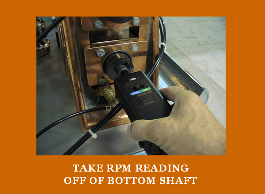
Some mill lines have digital readouts for the speeds of each section as outlined in the sample drawing below. If not, then use a digital hand held tachometer as outlined in the above picture to obtain the RPM readings from the bottom driven shafts in each of the sections.

Some operators feel they need to adjust the sizing section faster than the breakdown and fin section for proper pull and operation. This all depends upon the amount of "step up" between the sizing section and the forming section that is designed into the tooling, as well as how much thermal expansion the tube experiences in the cooling section after welding. Various methods of welding have various elongation rates. For example, those mills using high frequency welding will experience more elongation, or thermal growth than that of a tig welding application. If the tube is still "bouncing" in the coolant section, a slight increase in the trim in the sizing section may be required. Compare this visual observation to the RPM's and AMP readings of the sizing section. Insure the trim is not adjusted too fast, so the tooling is not "spinning" on the tube, resulting in the lost of drive, marking and premature tooling wear in this section.
This formula works for rounds and any shape on any tube/pipe mill line.
Use our contact form below to request more information on tube and pipe or roll forming products. All of our products and services have a 100% performance guarantee. If you are not satisfied in any way you will receive a free replacement or a complete refund.
Find more tube and pipe articles here.
Simply contact us here or call and get answers 24/7.
Contact Us (888) 953-9400
Roll-Kraft is pleased to announce the appointment of Mr. Mike Samplak to the position of Plant Manager at its headquarters facility in Mentor, OH.

Roll-Kraft is pleased to announce the appointment of Frank Lowery to Vice President of Roll Form Applications.

Roll-Kraft is pleased to announce the appointment of Kevin Gehrisch to the position of President.