


Subscribe To Roll-Kraft
Receive the latest news from Roll-Kraft.

Most tube & pipe producers will use common portions of a tooling set (such as the breakdown passes) to produce multiple tube sizes within a given range. The main purpose of sharing these breakdown passes is to save both on tooling costs and setup time. The thought is that since the fin passes are designed to work the strip edges (as well as accurately define the tube’s shape prior to welding) that sharing the breakdown passes for multiple tube sizes is acceptable. In most cases, the range of tube sizes which can share common breakdown passes should not exceed 20% (Figure 1).
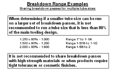
Figure 1: Limit the range of tube sizes using common breakdown passes to 20%
In addition to running strips for various diameter tubes through common breakdown passes, the tubes may also vary in material thickness. In Figures 2 & 3, the gauge variation is seen most prominently at the strip edges.
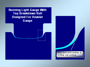
Figure 2: Running lighter gauge material with heavier gauge top roll
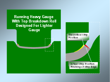
Figure 3: Running heavier gauge material with lighter gauge top roll
In Figure 3, running a heavier gauge material in a breakdown pass designed for a lighter gauge will create an interference condition at the strip edges. If the top spindle of this pass is raised to eliminate the interference, the remainder of the material will be improperly formed and a speed issue may also occur. A poorly formed tube entering the fin passes can result in the condition shown in Figure 4. The contour radius of the tube nearest the strip edges is the most important area to form in the breakdown passes.
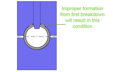
Figure 4: Improper formation of the tube entering fin passes
Not only does the range in tube size affect the formation of the tube, the strip width of the material is equally important to consider. Using the correct strip width is critical to producing good tube. The strip width of a tube is not calculated by using only the final outside tube diameter, but rather the gauge thickness, material grade and size of the tube at the welder. In welded tubes, the welded tube diameter is larger than the final desired tube diameter. This is done in order to “size” the tube down to the final diameter in the sizing passes, so the tube has to be larger at the weld station. In addition, a “weld allowance” is also required to be properly calculated into the strip width in order to compensate for material consumed in the welding/forging process. This weld allowance varies for HF and TIG welding. For example, the HF process consumes more material.
Another factor in determining the proper strip width is the number of fin passes used in the tooling set. Each fin pass applies force to the strip edges of the tube to not only force the outside surface of the tube to conform to the roll tooling contours, but also to reduce the outside periphery (OSP) of the tube gradually, while preparing the strip edges for welding. This reduction of OSP for each fin pass must be considered when calculating the strip width (Figure 5).
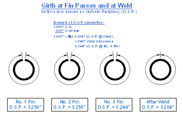
Figure 5: Example of reduction of OSP in the fin passes
The strip thickness and material grade are the last two factors to consider when calculating the strip width of a tube. As a tube is being formed, the outer surface of the material is elongated (stretched). At the same time, the inner surface of the material undergoes compression. When calculating the strip width of a given O.D. of a tube, the strip width will be narrower for thicker material than the strip width of a thinner material. This is why the designer must predict the amount of material stretch during forming in the tooling design. This stretch can also be called a “bend allowance”, where a percentage of the material thickness is used to calculate the proper strip width. The mechanical properties of the material, such as the yield strength and ductility (% of elongation) must also be considered in the strip width calculation. For example, materials with high yield strength and low ductility will not “stretch” as much as lower yield and higher ductility material (Figure 6), so therefore a larger bend allowance would be used in the strip width calculation.
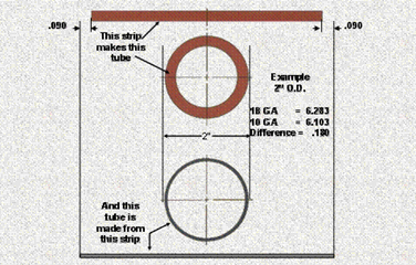
Figure 6: Example of strip width variation between two material gauges
While using dedicated breakdown and fin passes for each tube size and material gauge would be the ideal scenario for optimal production, most tube producers share breakdown passes for reduced costs and downtime. Shared breakdown passes will not form (stretch) the material as much as breakdown passes designed specifically for a particular size. In other words, the breakdown pass design is a factor in calculating the proper strip width and when there is too much variation in the formation of the tube, the strip width may not be correct if the design was based on using dedicated breakdown passes.
The information provided here is meant to increase awareness of the relationship between breakdown and fin passes as well as the strip width and the effect they have on one another in the production of your tubing.
If you would like to discuss this or any other topic in further detail, or have other tube or pipe production problems, Roll-Kraft is your customized solutions provider. Consult our website www.roll-kraft.com for additional related information or contact us directly at 888-953-9400.
Online Strip Width Calculator
Having difficulty determining the ideal strip width calculation for your tube mill, pipe mill or tube and pipe equipment? Use our strip width calculator to make your job much easier.
All you need is the following information:
Material Type
Weld Diameter
Gage Thickness
Design Type
Number of Fin Passes
Our strip width calculator will then tell you the estimated strip width for high frequency, low frequency, laser and TIG weld types.
Click here to determine your strip width calculation.
Have questions about determining your strip width calculation or any other tube and pipe or roll forming products and services? Use our Quick Contact Form or Ask the Doctor.
All Roll-Kraft products and services have a 100% performance guarantee. If you are not satisfied in any way you will receive a free replacement or a complete refund.
Simply contact us here or call and get answers 24/7.
Contact Us (888) 953-9400
Roll-Kraft is pleased to announce the appointment of Mr. Mike Samplak to the position of Plant Manager at its headquarters facility in Mentor, OH.

Roll-Kraft is pleased to announce the appointment of Frank Lowery to Vice President of Roll Form Applications.

Roll-Kraft is pleased to announce the appointment of Kevin Gehrisch to the position of President.