


Subscribe To Roll-Kraft
Receive the latest news from Roll-Kraft.

Proper tube mill setup is critical to achieving consistent tube quality, minimizing scrap, reducing downtime, and improving overall production efficiency. In this guide, Roll-Kraft walks through the core setup procedures used throughout the breakdown, fin, weld, and sizing sections of a tube mill. The videos and supporting explanations below demonstrate practical setup techniques, adjustment methods, and validation procedures that help operators establish more stable and repeatable mill performance. Use the quick reference guide below to jump directly to each section of the setup process.
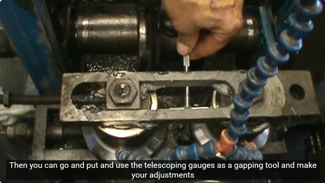
The setup process begins by establishing the correct rim clearances for the side roll passes. The tooling can be set by returning to documented rim clearances from the last successful run, or by taking the dimensions directly from the setup chart when working with a new or reworked roll set.
For wider rim clearances, a set of calipers is first set to the required dimension. Telescoping gauges can then be used as a gapping tool to transfer that measurement into the side roll pass rims and make the necessary adjustments. For narrower rim clearances, feeler gauges can be used to pregap the side roll passes.
After adjustment, the video emphasizes checking that the rolls are parallel with a straight edge. Parallelism is verified again later once the mill is loaded and final sizing checks are being made.
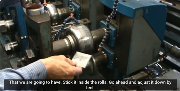
Before the mill is threaded, the breakdown rolls are pregapped so the tapered strip can pull through the mill more smoothly. Cut a small piece of material from the same coil that will be run and place it inside the rolls.
The initial adjustment is made by feel. The operator notes that most experienced operators develop a sense for how much pressure to apply. That initial feel-based setting is later validated with solder to confirm the pressure is not too tight.
The same approach is repeated through each breakdown pass so the strip has a better chance of feeding successfully through the mill during threading.
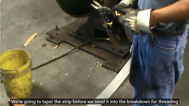
The end of the strip is tapered before it is sent into the breakdown section for threading. Lighter gauge material can be tapered with tin snips, while heavier gauge material can be tapered with a grinder and abrasive cutoff wheel.
The goal is to create a point that can be grabbed by the drive point in the breakdowns. The taper also provides a lead-in effect as the strip moves into the fin section.
Once tapered, the material is paid off into the entry system, passed through the guide rolls, and pushed up to the breakdown. When the mill starts, the taper helps pull the strip into the breakdown rolls.
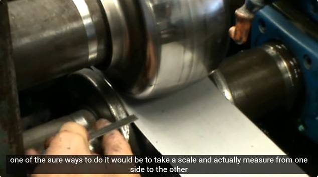
After the mill is threaded, the entry table needs to be centered to the first breakdown pass. Operators often make this judgment visually by looking at both sides of the strip and checking whether the distance from the edge of the strip to the outside of the bottom roll appears equal on both right and left sides of the first breakdown pass.
A more precise method is to use a scale and measure from one side to the other. The objective is to confirm that the strip is centered and producing an even edge form coming out of the number one pass.
If even edge form is not achieved at the first breakdown, it will be difficult to correct later in the mill.
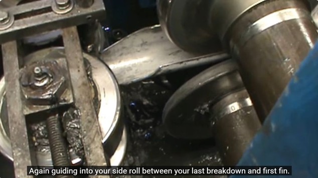
With the breakdown rolls pregapped and the strip tapered, the material can be threaded through the breakdown and fin sections. The tapered strip enters the first breakdown, moves into the second breakdown, and continues through the third breakdown.
From there, the strip guides into the side roll pass between the last breakdown and the first fin, then continues through the fin section. The long taper provides a smoother guide into each station and helps prevent fold-over in the fin section.
On high-frequency weld mills, monitor the impeder and induction coil carefully during threading. Threading continues through the weld box and on into sizing.
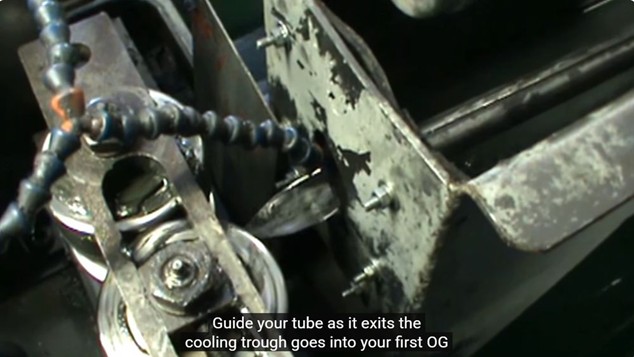
After the weld box, the tube is carefully guided through the coolant section and into sizing. The tube exits the cooling trough and enters the first OG and sizing passes.
Check for anything that could catch the tube as it moves through the coolant section, including support rollers or other components in the path.
The tube then proceeds from the first sizing pass into the 1-2 side roll, then into the second sizing pass, 2-3, and finally the last sizing section.
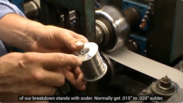
Once the strip has been fed into the mill, solder can be used to check the pressure of the driven breakdown stands. The operator uses .015 inch to .020 inch solder and tears off one segment for each breakdown stand.
The solder is placed on top of the strip at the front of each stand and jogged through the rolls. Afterward, the operator examines the squeeze pattern and checks whether it is even across the width. The thinned solder can be measured with a 0 inch to 1 inch micrometer or a set of calipers.
The goal is to achieve the same pressure in each breakdown pass. Applying the same feel to different breakdown rolls can create problems, especially where narrower top rolls are involved, because too much pressure can de-gauge the strip.
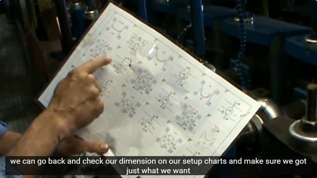
After the tooling has been pregapped and the mill has been threaded, the setup chart is used to confirm that the dimensions match the required values. A practical time-saving step is to write the setup chart dimensions directly on the stand or tower.
By marking the appropriate dimensions near the relevant side roll and fin section, operators can make adjustments without constantly returning to the setup chart. This is especially useful as tooling wears and settings need to be maintained throughout the forming process.
The figures remain visible where the operator needs them, helping the setup process move more efficiently.
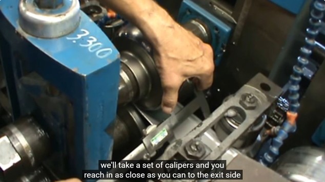
To set the side pass stands, check the pass with calipers by reaching in as close as possible to the exit side. The reading is compared against the setup chart value written on the stand.
The same process is continued down the line, with adjustments made as needed to match the setup chart dimensions.
This section reinforces the importance of checking each pass and using measured values rather than relying only on visual judgment.
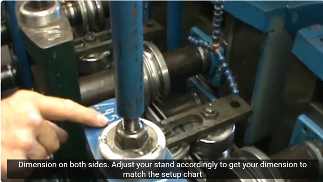
Verifying equal dimensions on both sides of the fin section
The driven passes in the fin section can be checked by measuring on the exit side of the driven passes on either side of the tube with a micrometer. Check both sides of the strip to confirm that the dimensions are even.
The OSP dimension is checked by using a Pi tape as outlined in the video. The setup chart has the dimensions for the tube measurement when using a micrometer as well as the OSP measurement.
To set the side pass stands, check the pass with calipers by reaching in as close as possible to the exit side. The reading is compared against the setup chart value written on the stand.
After any adjustment, use a straight edge to confirm that the driven and side pass tooling remains parallel.
This process helps ensure the fin section is set consistently and is preparing the edges of the strip before the tube proceeds into the weld section.
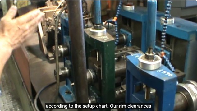
Feeler gauges can be used to confirm consistent rim gaps and shaft parallelism.
One way to check parallelism and confirm that rim gaps are consistent is by using feeler gauges. Select feeler blades and check for the same drag/gap between the rims through the pass and compare to the setup chart.
Solder provides a quicker and more accurate method for checking the driven passes. Using solder that is thicker than the rim gap on the setup chart, place solder ahead of the rims of the tooling, jog the mill to pass the solder between the rims, and then check thickness with micrometer or calipers.
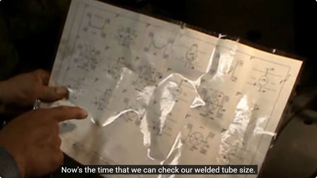
Verifying welded tube size and roundness before entering the sizing section.
Once the strip has been jogged through the weld box and a weld has been established, the welded tube size can be checked against the setup chart. In this example, the target welded tube size is 1.270 inches.
A Pi tape can be wrapped around the tube to measure overall tube size. However, the operator explains that this does not confirm roundness. To check roundness, measurements should be taken at the top, side, and diagonals using a micrometer.
The weld rolls can be adjusted tighter or looser to reach the proper tube size before sending the tube into sizing.
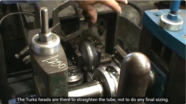
The sizing section finalizes tube dimensions while Turks heads help straighten the tube.
The sizing section sizes and stress relieves the tube. It is important to achieve a round tube size out of each driven sizing stand.
The side roll passes and driven passes are adjusted as needed to achieve the correct round tube size out of each driven stand.
Turks heads are there to straighten the tube, not to perform final sizing in a round tube.
The series concludes with the mill running smoothly after the setup process has been completed. The overall sequence demonstrates how each step supports the next: presetting, pregapping, tapering, centering, threading, checking pressure, verifying dimensions, setting the breakdown, fin, weld, and sizing sections.
The practical takeaway is that a successful tube mill setup depends on measured, repeatable procedures. Setup charts, calipers, micrometers, feeler gauges, telescoping gauges, solder, Pi tape, and straight edges can all be used to confirm the mill is properly set instead of relying on guesswork alone.
Have questions about your tube mill setup process or need help troubleshooting a production issue? Roll-Kraft provides tube and pipe tooling design, technical support, setup assistance, and project quoting support for manufacturers worldwide. Visit our Contact Us page to speak with our team about your application, tooling requirements, or production challenges.
Simply contact us here or call and get answers 24/7.
Contact Us (888) 953-9400
Roll-Kraft is pleased to announce the appointment of Mr. Mike Samplak to the position of Plant Manager at its headquarters facility in Mentor, OH.

Roll-Kraft is pleased to announce the appointment of Frank Lowery to Vice President of Roll Form Applications.

Roll-Kraft is pleased to announce the appointment of Kevin Gehrisch to the position of President.